Review on Perceiving Accurate CSI Phases with Commodity WiFi Devices
Introduction
After reading the paper ‘Perceiving Accurate CSI Phases with Commodity WiFi Devices’,I got some new knowledge of the way how to handle inaccurate CSI measurements which we can get from commodity wifi devices.
The Channel State Information (CSI) describes how a signal propagates from the transmitter to the receiver and represents the combined effect of, for example, scattering, fading, and power decay with distance.CSI has been recently used for various motion- or location-based applications.As a result, accurate CSI measurements are of great significance to tremendous applications.
However,because of the hardware imperfection,CSI phase measurements includes various errors besides true CSI phases,for example, Carrier Frequency Offset (CFO),Sampling frequency offset (SFO),Packet detection delay (PDD) and PLL Phase Offset (PPO).In this paper,the author Zhuo not only remove these errors mentioned above,but also identify the unknown non-negligible non-linear CSI phase errors and then remove them from CSI measurements.After that,we can get accurate CSI measurements.
Known Errors
As we said above,because of the hardware imperfection,CSI phase measurements includes various errors besides true CSI phases.Fig.1 illustrates signal processing in 802.11 n.We can analyze the source which causes the errors through Fig.1.
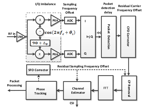
Fig.1
CFO : Carrier Frequency Offset (CFO) which is caused by the unsynchronized central frequencies of a transmission pair leads to a time-varying CSI phase offset across subcarriers.
SFO : The sampling frequencies of the transmitter and the receiver exhibit an offset(SFO) due to non-synchronized clocks, which can cause the received signal after ADC a time shift with respect to the transmitted signal.Then the time shift causes phase rotation errors.
PDP : Packet detection delay(PDP) stems from energy detection or correlation detection which occurs in digital processing after down conversion and ADC sampling.Packet detection introduces another time shift with respect to the transmitted signal , which leads to packet-varying phase rotation error.
PLL : The phase-locked loop (PLL) is responsible for generating the center frequency for the transmitter and the receiver, starting at random initial phase. As a result, the CSI phase measurement at the receiver is corrupted by an additional phase offset.
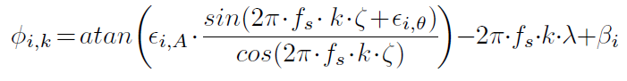
From the above known error sources, the measured CSI phases are mainly distorted with various phase ration errors and/or phase offset errors.For a transmission pair, the phase measurement (i, k) for sub-carrier k in band i can be expressed as
 (1)
(1)
where k ranges from -28 to 28 ( index 0 is reserved for carrier frequency) in IEEE 802.11n for 20MHz band width, ( i, k) denotes the true phase, is the timing offset at the receiver, including time shift due to PDD and SFO, f is the sub-carrier spacing between two adjacent sub-carriers (i.e. 312.5KHz), is the total phase offset, and Z is the additive white Gauss measurement noise.
Note that, except for Z, other reported phase errors are linear with sub-carrier indexes.
Unknown Errors
Experiments
In order to verify the conclusion ‘phase errors are linear with sub-carrier indexes’, Zhuo conduct conduct an experiment in a typical indoor environment with the length and width of the room being 12 meters and 10 meters with Atheros AR9380 Nics. They arrange the transmitter and the receiver in strong line-of-sight (LOS) condition with distance of 0.5 meter, and make the transmitter to transmit with its first antenna, denoted as Nc1, with a fixed transmitting power of 5dBm and the receiver to receive with all of its three antennas denoted as Nr1, Nr2 and Nr3 respectively.
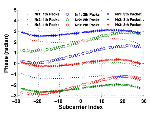
Fig.2
Observe non-linear errors
Figure 2 illustrates three groups of unwrapped CSI phase measurements for three consecutive packets, with each group containing CSI phases for 1 by 3 transmission pairs.According to (2), the ideal phases on different sub-carriers should be almost linear with the sub-carrier indexes. They observe, however, obvious non-linear distortions in all unwrapped phase measurements.They repeat such experiment in an indoor gymnasium with length of 50 meter and width of 30 meter, and get similar results.
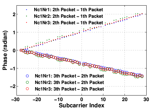
Fig.3
Exclude the possibility of environmental instability
They think perhaps the unstable environment causes these unknown non-linear errors.According to previous work12, if the wireless channel is stable, the unwrapped phase differences of two consecutive packets for the same transmission pair are almost linear.After removing the phase offset at sub-carrier #-28 from each CSI phase measurement, we calculate the CSI phase differences of each transmission pair between any two consecutive packets using the same CSIs in Figure 2 and plot the results in Figure 3. It can be clearly seen that the unwrapped phase differences of two consecutive packets for the same transmission pair are almost linear with the sub-carrier index, indicating that the environment is quite stable.
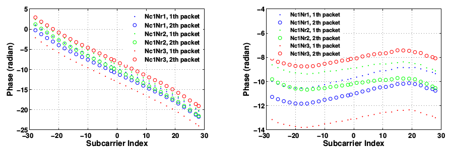
Fig.4(a) Fig.4(b)
Exclude the possibility of specific Nic
Although they demonstrate that the environment is quite stable,maybe these non-linear errors are specific to Atheros AR9380 Nics.They repeat the experiment except that we change to use Intel 5300 NICs and draw the unwrapped CSI phase measures of two packets in Figure 4(a).After compensating 4 sampling periods, i.e., 200 ns, they plot the corrected CSI phases in Figure 4(b). It can be seen that the envelopes of phase measures are similar to Figure 3(a).
Conclusion
The default assumption that only notable linear phase error exists cannot hold and an unrevealed nonlinear phase error exists, which cannot be mitigated through existing methods. To make matter worse, obviously this nonlinear error is orders-of-magnitude higher than the ground truth phase and thus non-negligible.
They augment the CSI phase error model as
 (2)
(2)
where denotes the non-linear error as a function of the sub-carrier index k in band i, with other parameters the same as in (1).
Remove Non-linear Phase Errors
Intensive Experiments
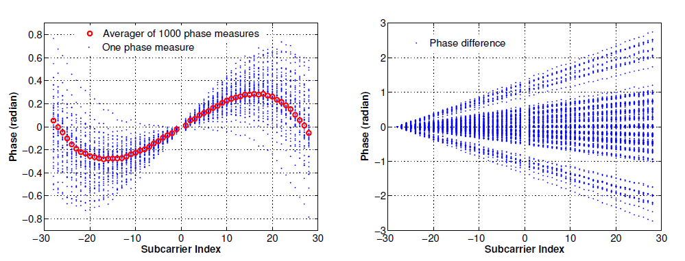
Fig.5(a) Fig.5(b)
In specific, they use a RF cable of 30cm and an attenuator of 50dB to connect the first radio chains of both the transmitter and the receiver. The transmitter sends 1,000 packets within three seconds each time with a fixed transmission power of 15dBm in a 20MHz band with a central frequency of 2,412MHz. They random select 100 CSI measurements, remove the mean from each CSI phase measurement, and plot the unwrapped CSI phases and the phase differences for any two consecutive phase measures in Figure 5(a) and (b), respectively.
From Figure 5(a) and (b),they get two observations:
- the envelopes of unwrapped phases are not linear but symmetrical and analogous to some form of trigonometric function
- the phase differences of consecutive packets are linear with sub-carrier index
A direct conversion receiver uses two quadrature sinusoidal signals to perform the quadrature down conversion. This process requires shifting the local oscillator (LO) signal by 90 degrees to produce a quadrature sinusoidal component. When mismatches exist between the gain and phase of the two sinusoidal signals and/or along the two branches of down-conversion mixers, amplifiers, and lowpass filters, the quadrature baseband signals will be corrupted. Once I/Q imbalance exists, after sampling and FFT, the NIC would estimate and report an anamorphic CSI.Thus,when there is only one path between a transmission pair, they assume the averaged phase measurement of subcarrier k in band i as:
 (3)
(3)
where and denote the gain mismatch and the phase mismatch for band i respectively due to the IQ imbalance problem, is an unknown timing offset, is the equivalent timing delay caused by time-of-flight, PDD and SFO, and is a phase offset error.
Least-square Regression Analysis
To verify the validity of (3), they then apply the least-square regression analysis to the average of the 1,000 CSIs measured via a short RF cable as described in above subsection. The significance of the regression is measured by the coefficient of determination , defined as
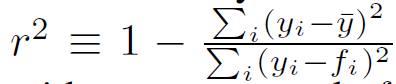
where is the averaged CSI phase with mean and is the modeled/fitted value.
Root Source
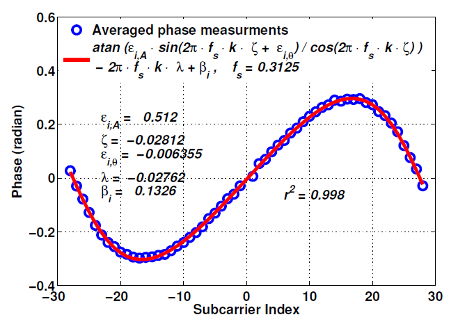
Fig.6
As shown in Figure 6, the averaged CSI phase measurements are very well approximated ( > 0.998) by the model in (3). They repeat this exercise in all bands and with all NICs and obtain similar results. As a result, they claim that the IQ imbalance problem is the root source of non linear CSI phase errors.
Characteristics of Non-Linear Phase Errors
experiments
In specific, they use combinations of different attenuators of 30/40/50/60 dB and transmitting powers of 15/10/5 dBm to achieve various signal strength. In addition, the transmitter and receiver hop synchronously among six different bands once 1,000 CSIs are collected and averaged on one band. For each configuration, they repeat the data collection for 200 times in a duration of two weeks and for each time we conduct the least-square regression analysis to the averaged CSI to derive all parameters in (3).
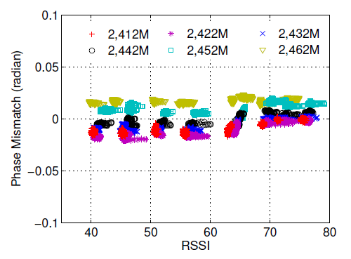
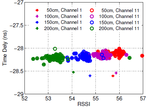
Fig.7
They observe two characteristics from Fig.7:
- The phase mismatch is sensitive to the frequency bands
- is independent of frequency bands and the time-of-flight of signal.
Remove Non-linear Phase Errors
From the above study, they have one key observation that non-linear CSI phase errors caused by IQ imbalance are relatively stable over time and various RSSI conditions but sensitive to frequency bands.If the parameters of , and are known, non-linear phase errors can be removed.
On one hand, if there is only one dominant path between a transmission pair, least-square regression analysis as described in Subsection III-B can be conducted but in real world multipath is inevitable.On the other hand, if a measured CSI phases can perfectly fit the model in (3), it means that either only one dominant path exists (e.g., in a strong LOS and weak multipath environment) or multipath is counteracted.
Thus ,when determination is larger than a threshold,we think this CSI phases is postive.With Adequate postive CSI measurements ,we can easily remove non-linear phases errors.
Remove Linear Phase Errors
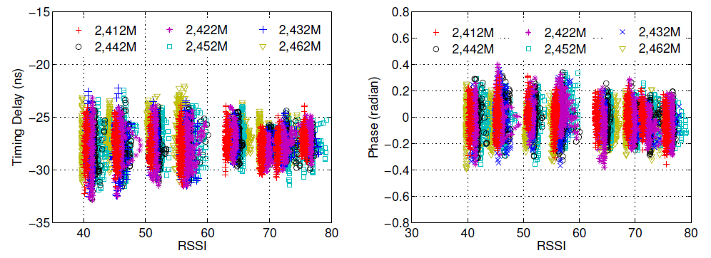
Fig.8
From intensive experiments mentioned above,they draw Fig.8 which plot the derived parameters related to linear CSI phase errors.We have the following four main observations: 1) the timing delay introduced by PDD and SFO in (4) is independent of frequency bands and RSSI conditions; 2) on a particular band and in a relatively stable RSSI environment, the timing delay follows a nonzeromean Gaussian distribution; 3) the variance of the Gaussian distribution of is large; 4) the phase offset error is analogous to the timing delay except the mean of its Gaussian distribution is zero.
From previous analysis above,though the linear (or rotation) CSI phase errors introduced by PDD and SFO are Gaussian distributions, due to large variance, it is infeasible to get the mean by averaging a small number of CSIs measured within the channel coherence time.In order to eliminate phase rotation errors, they leverage the key insight that, given that the wireless channel is stable, the channel phase response for one specific frequency in passband should be the same even when it is measured from different bands.
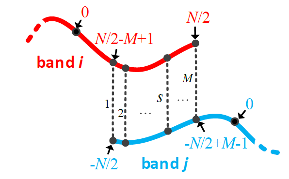
Fig.9
As illustrated in Figure 6, suppose there are M overlapping subcarriers between band and band both of which contain N non-zero indexed subcarriers exposed in the CSI measurements. The and ,for s [1,M],should be identical.Thus they have
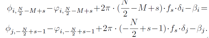 (4)
(4)
Given that and are averaged CSI phases and the non-linear phase errors and can be estimated, there are only 4 unknown parameters,i.e., , , , and for M equations.For overdetermined equations (i.e., M is larger than 4 for commodity WiFi devices), they adopt the method of ordinary least squares (OLS) to find an approximate solution.